Recently I was asked if I would contribute tech more often, while there isn't a whole lot to share, I thought I would post up some pics of a custom LT1 intake manifold we built about 10 years ago now. There are actually two of these, we constructed them for two Impalas and split the fabrication duties between us. I still have this one, the other left when the car was sold and its current whereabouts are unknown.
The impetus for this change was a prototype expanded plenum that was purchased from a Corvette race shop. The “Forced Air” lettering implies it came out of the AO Engineering, a company that used to make specialty Corvette parts, but is now defunct. Here are a couple photos of their Cold Air Intake that replaces the front license plate with ducting to feed cold air directly to the air filter housing.
Intake system:

Plate duct:

The story I was told is that the plenum was created to - and testing proved it did - help midrange & top-end power without sacrificing low-end torque. It was intended to retrofit to the early (no crossover) LT1 intake manifold by milling off the top surface and tapping 8 screw holes in the vertical walls. How many were actually made is anyone's guess, but we have never heard of another.
At the time, the only aftermarket intake for an LT1 was the exorbitantly expensive Superram intake; it probably would have sold in decent numbers but for some changes made to the factory intake. If you have ever had a set of '92 or '93 LT1 fuel rails in your hands, you may have noticed that the fuel lines are located to the rear. To ensure that the front cylinders are not starved for fuel, the rails themselves are a complex double path extrusion that includes a full length fuel passage so that the incoming fuel is delivered to the front of the rails and then fills the injector galley on its way back to the regulator connection. At some point somebody recognized that they could save some cost by moving the crossover to the front and specifying a single passage rail extrusion. And about the same time the fuel lines were changed from stainless steel to plated mild steel in another cost reduction.
When the '94 LT1's were released, the intake was modified with a trough just behind the throttle body to permit the forward crossover. Other that not looking quite a sleek as the earlier arrangement, most never cared either way, but the plenum extension was immediately obsoleted, and since the B and Y Bodies were the only cars that could make use of the extension anyway. (F-car engine location prevents is use on those cars, at it would be a challenge just to clear the cowl, and even more so to remove & replace with the engine installed.)
So we had this plenum and how to make use of it with the later intake? Remembering how Mopar drag racing oil pans make use of a hollow passage in the pan to allow the centerlink to pass through, inspired the idea of making a subplate to isolate the crossover in the same manner.
After locating a late intake, the top was milled to remove the raised ribs and true up the mounting surface. Then rectangular openings located before & after the crossover were cut. Finally multiple holes were drilled and tapped in the top surface for 6-32 fasteners.
A subplate was fabricated out of 1/4” aluminum plate and drilled with both the intake manifold and raised plenum bolt patterns. Hand-cut gaskets finished up the project. Chris (SWT SS) decided he wanted something unique for his car so we worked out a trade and installed it on his Impala. This manifold was completed before I had access to a digital camera, so I only have some photos I was able to locate on his Photobucket account to share here.
Modified intake with gasket in place:

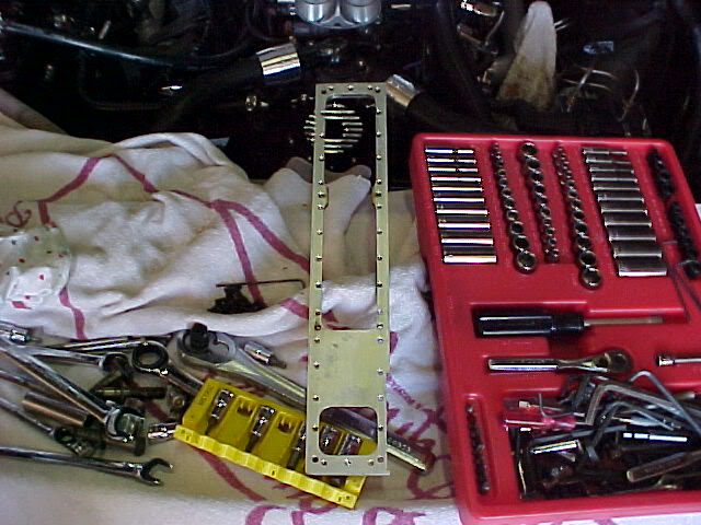
1/4” subplate showing countersunk holes for 6-32 fasteners and the tapped holes for 10-32 capscrews to attach the upper plenum:
Later he sent it out to be chrome plated. Here are a couple photos of it as installed:
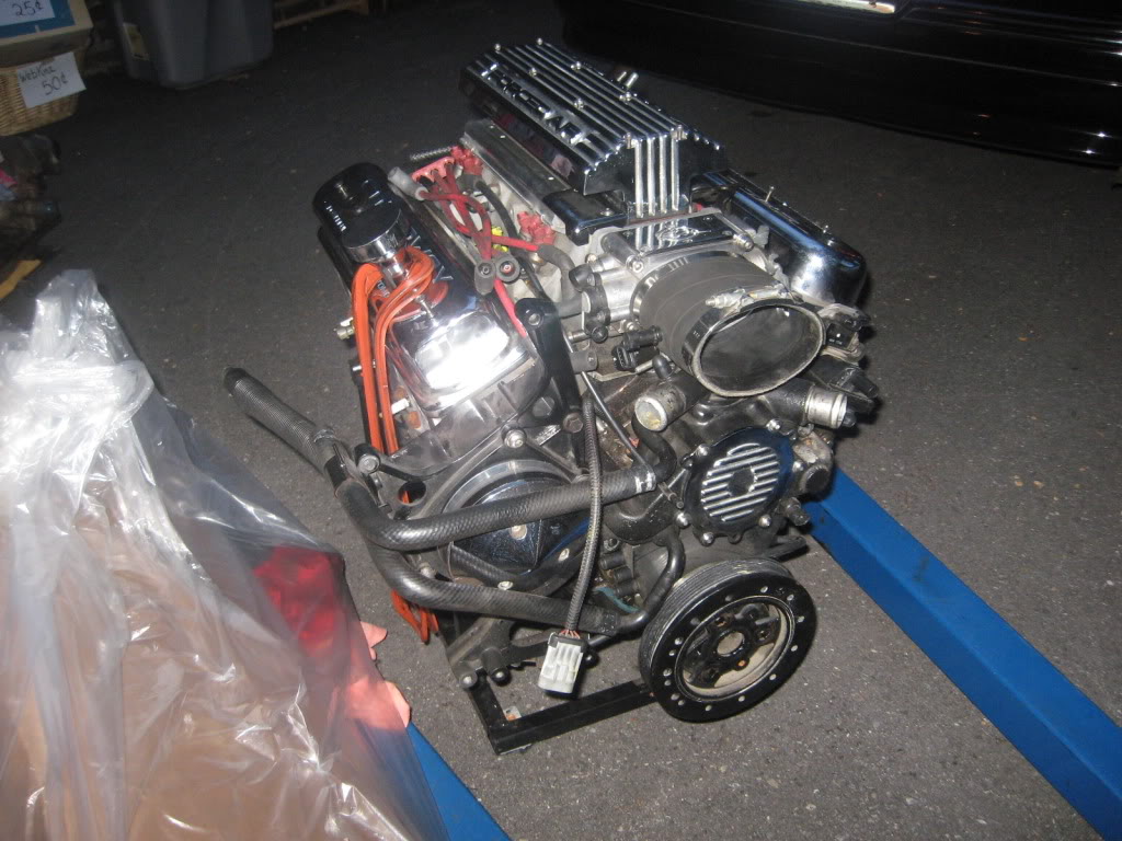
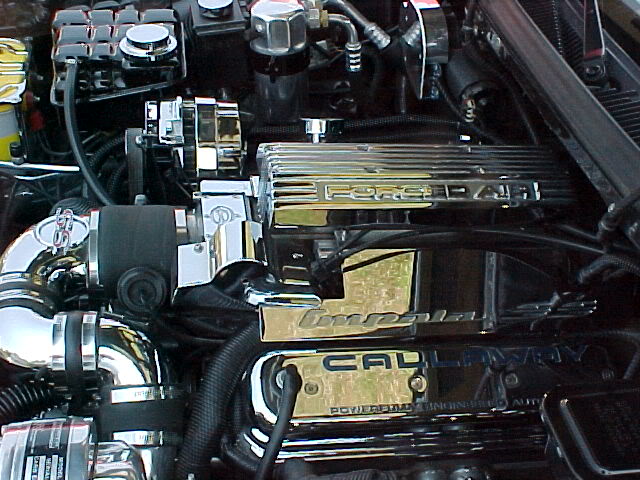
Once the first system was up & running, it wasn't long before talk turned to making a couple more setups. We located a length of hexagonal aluminum extrusion that looked to be about the same width across the flats as the top of the intake, and sufficiently long enough to construct two manifolds. Here's how things transpired:
Note: The manifold shown below has been sitting on the shelf for nearly 5 years now. The only reason it isn't still in service is the original engine was replaced to install a dedicated turbocharged engine assembly. It is still pretty much as it came off the car, so it hasn't been fully cleaned and detailed prior to taking these photos.
We started by milling the top of the manifolds and tapping them for the 6-32 fasteners:
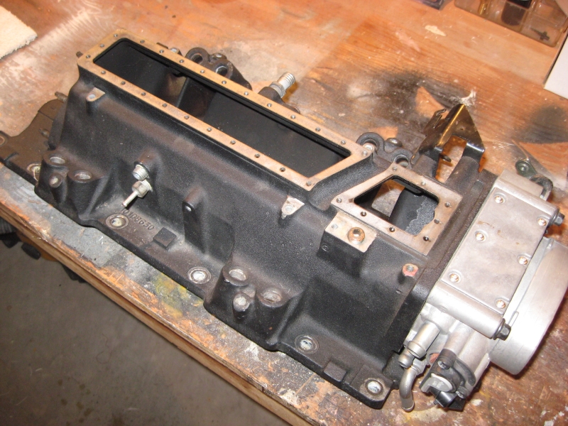
The fuel rails are installed next:
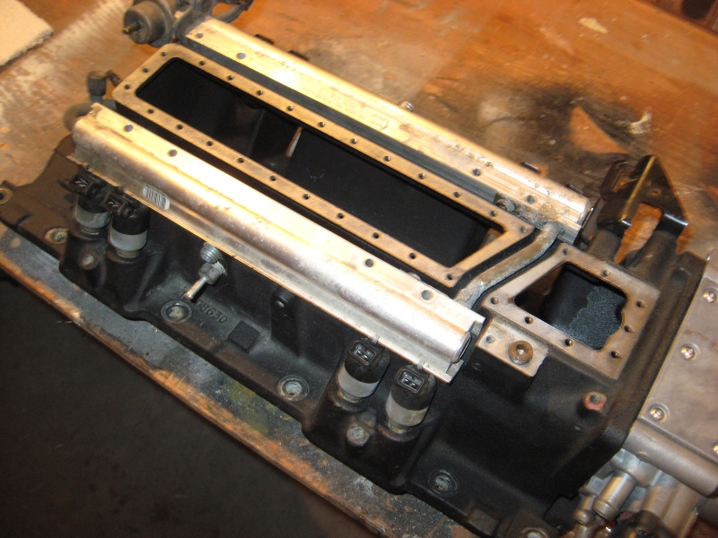
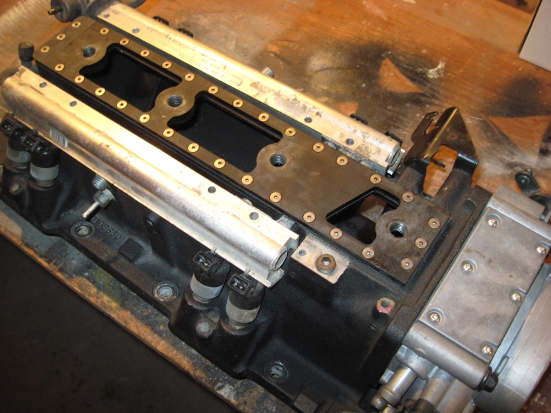
As before, subplates were fabricated to mate the intakes & plenums. Here the lower gasket has been set into place and the subplate bolted down:
Front & rear plates were constructed to cap the new plenums. This time though, there was the desire to integrate the look of the completed engines, both of which were using the Corvette composite valve covers:
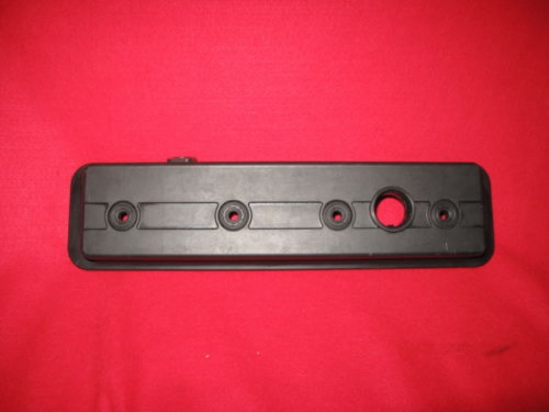
So the cover reliefs were replicated in the top surfaces:
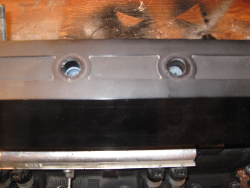
Four holes were cut into the tubing and vertically mounted tubes were fitted to isolate the holddown bolts from the intake volume.
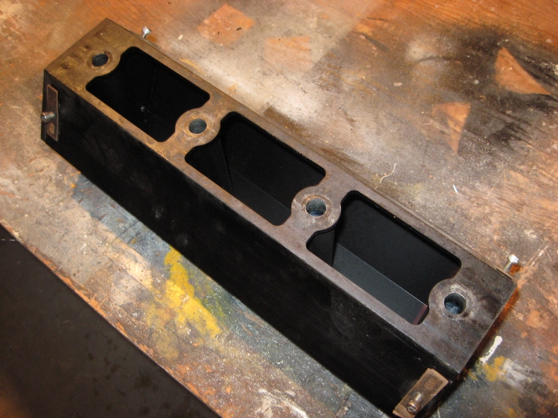
A decorative front plate was fashioned to cover the front of the plenum:

Additional side plates (with mounting brackets) were fabricated to smooth the transition between the angled plenum and Corvette fuel rail covers. The plenums, endplates & isolation tubes were then sent out for to be welded into complete units.
After the welding was finished, the plenums returned to the machine shop to true up the welded surfaces and tap the mounting holes for the decorative plates. After the final machining was complete, everything was sent out for black anodizing, and the front & side plates were engraved.
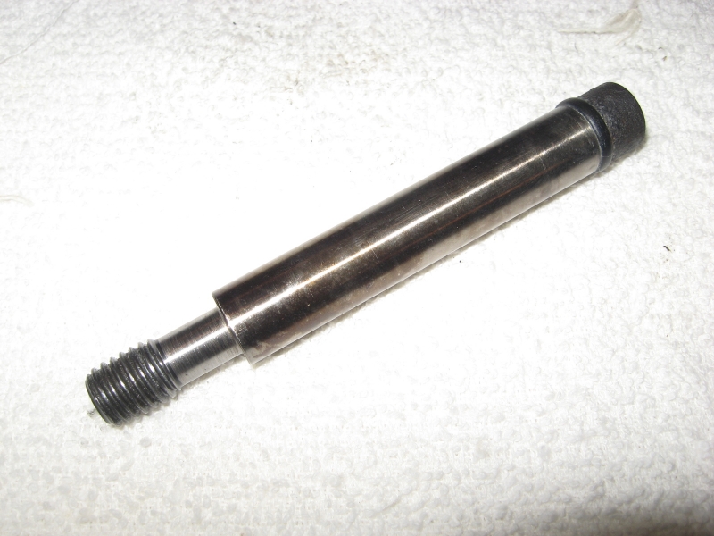
While the outside work was being completed, shouldered socket head capscrews were cut down and fitted with O-ring grooves to seal the shafts, as the threads are exposed to intake vacuum. The tops of the bolts were then drilled & tapped to accept the special composite valve cover top screws, purchased from GM. In his application, instead of actually retaining the plenum as they would the valve covers; they serve as decorative caps to keep dirt & water from entering the isolation tubes.
Plenum retaining bolt with O-ring seal:
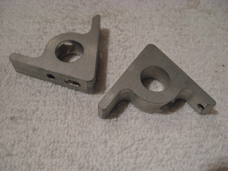
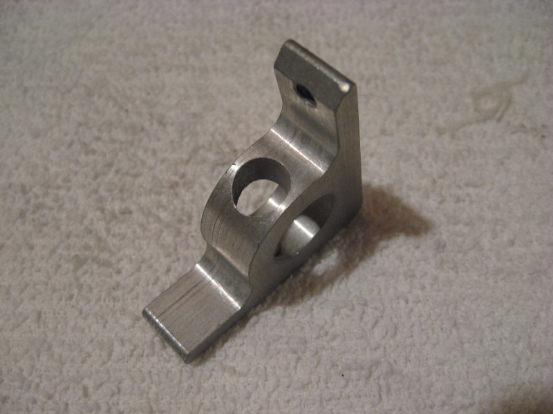
Triangular support brackets to mount the side plates to the plenum, and an angled bracket that relocates the MAP sensor to the side of the intake manifold completed the fabrication work.
Support brackets:
Plenum bolted down:
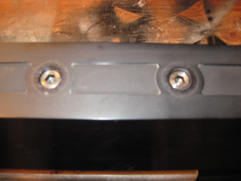
Corvette valve cover screws installed:

Support brackets installed:

The existing MAP sensor location interfered with the plenum, so the port was tapped to accept a 1/4” NPT plug. The MAP sensor is relocated to the side of the intake with the angled bracket (not shown) and is now supplied from a tee fitting from the HVAC connection. Close up of a side plate support bracket and the MAP sensor plug:
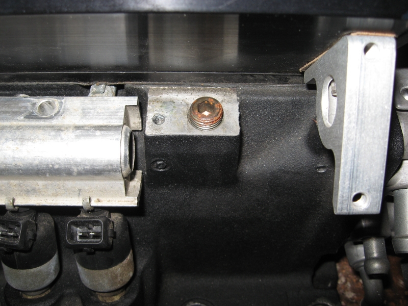
Side plate attached:

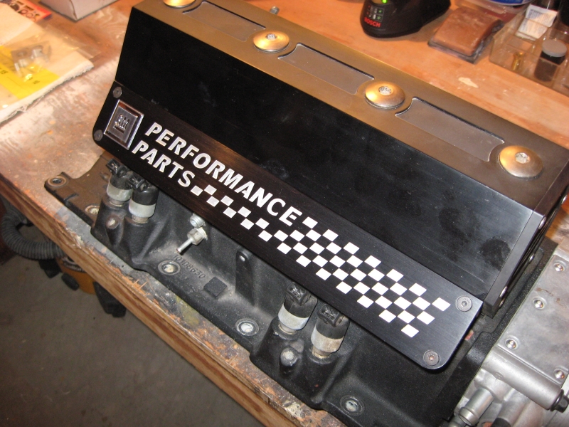
Completed assembly, minus the Corvette fuel rail covers:
[/img]
The intake is waiting for an engine to install it on, not sure if that will be one of mine, or if it will find its way to eBay, but that pretty much sums it up for now.
Enjoy,
- J
